随着海运经济的不断发展,集装箱船也在技术和经济效益的驱使下,不断突破着尺寸上的极限。在马士基3E船型面市的短短几年里,集装箱船就已经进入了24000TEU的时代。作为世界范围内集装箱起重机生产商中的佼佼者,ZPMC也一直在努力推动着产业的技术进步,新技术新产品层出不穷。继成功推出3E型岸桥之后,ZPMC的工程师团队又很快推出了3E plus岸桥,并在应用中取得广泛好评。
众所周知,随着码头装卸设备的大型化,其对于码头的土建也提出了更高的要求,更大的起重机参数需要更高的许用轮压和更强的防风装置来匹配。尤其是对于沿海各大码头来说,风对于设备的影响,一直都是一个绕不开的话题。在对设备结构进行优化的过程中,我们也始终将风的影响作为重要的考量因素。因此,ZPMC开发出了一种新的结构设计理念——半圆形大梁岸桥(ZMH Boom),以该概念的首席设计师张明海先生命名。

结构形式
这种起重机的主要特征在于对主梁结构进行的优化,主梁主要由上面板、位于上面板下方的承轨梁腹板和与腹板对接的圆弧形板。上面板为沿纵向延伸的水平直板;小车轨道梁位于上面板在宽度方向上的两端,承轨梁腹板与上面板对接的位置分别位于小车轨道的正下方,承轨梁腹板与上面板之间保持一个接近90°左右的夹角。这样既能有效传递受力,又便于与圆弧形板的对接;圆弧形板由平板拼接而成,然后折弯成所需的形状,对接于承轨梁腹板的延伸线上。起重机主梁内部还包括沿着纵向贯穿的纵向筋和U形钢,以及沿纵向间隔设置的隔板。由此,我们可以得到一个近似于半圆形截面的大梁结构。详见附图1。
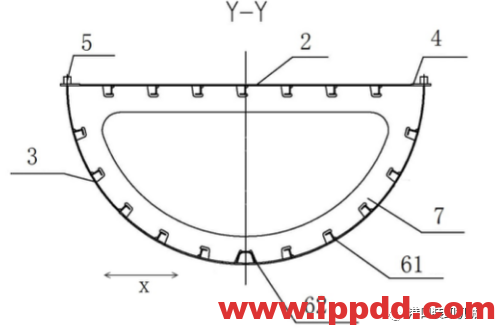
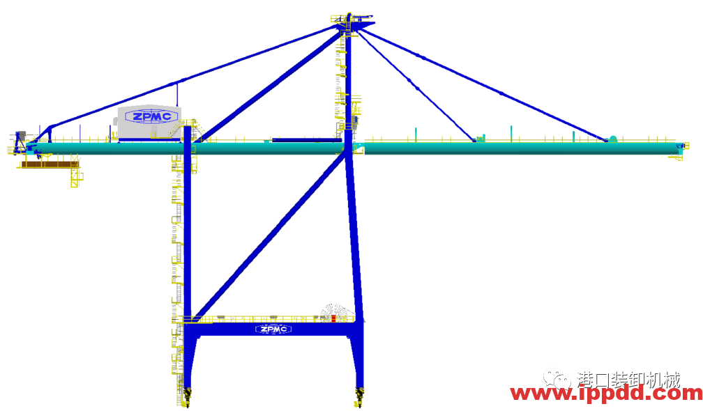
采用上述大梁结构形式时,大梁铰点可采用单铰点形式置于大梁上表面的下面或上面,结构形式简单、紧凑,日常检修维护方便。小车轨道布置在大梁的上表面,这样可以保障制造和安装的精度,避免轨道的后期调整。因此,轨道可以焊接在承轨梁上,减少了今后轨道压板和轨道垫的大量检修工作。大梁内部采用U形纵向筋,既能根据受力的强度需要用不同的板厚调整,还留出了内部检修通道,方便人员安全通行。
小车的主要驱动机构等均布置在大梁上方,装配、测量、调整都更方便。大梁的上表面可以直接作为安全的走道和维修平台;由于下表面是弧形的,两侧有更多的空间来布置辅助件,也可以进一步优化小车的下部结构和大梁之间的空间。
分析
该结构形式与现有单箱梁设备相近,对于码头现有的操作习惯和管理模式影响不大。基于多年的理论研究和实际生产的经验积累,我们知道,在岸桥作业状态下,轮压(海侧)的最大值通常出现在小车在大梁的最前端满载作业时;而在锚定状态下,大梁仰起,整机重心后移,轮压(陆侧)的最大值通常出现在风从海侧吹向陆侧的时候(仅作理论分析,未考虑角度风及不同码头实际的季风方向),而且此时的海侧上拔力也是最大的。
新型的半圆形截面大梁,相比于以往的箱型
截面,可以有效降低结构的风力系数。根据FEM设计规范,我们可以查得,圆形截面的风力系数为0.7左右,对比于矩形截面所常规选用的1.4-1.8的风力系数,下降了百分之五十以上。随着风力系数的减小,作用在前大梁上的风力也随之减小,以往为了满足暴风工况下大梁安全性所增加的板厚和结构重量也可以进行一定程度的优化。而大梁重量的优化,进一步降低工作状态下的最大轮压值。另外,由于降低了作业状态下的侧向风力对大梁的影响,对于起重机在最大外伸距位置的侧向刚度也有所改善。
初步对比
我们在数据库里调用了两个已完成的项目数据,进行了一个初步的对比分析。其中设备一的前伸距为65米,轨距30米,后伸距20米,轨上起升高度45米,起重量65吨。设备二的前伸距为50米,轨距30米,后伸距16米,轨上起升高度38米,起重量61吨。我们引入风速和轨距两个变量来考量采用新型大梁设计时,轮压数据的变化情况。降幅如下表:
|
设备一 |
工作时轮压(海侧) 工作风速25米/秒 |
非工作时轮压(陆侧) 非工作风速42米/秒 |
非工作时轮压(陆侧) 非工作风速55米/秒 |
非工作时轮压(陆侧) 非工作风速70米/秒 |
|
轨距24米 |
4% |
5.6% |
8.2% |
10.8% |
|
轨距30米 |
3% |
4.9% |
6.7% |
9% |
|
设备二 |
工作时轮压(海侧) 工作风速25米/秒 |
非工作时轮压(陆侧) 非工作风速42米/秒 |
非工作时轮压(陆侧) 非工作风速55米/秒 |
非工作时轮压(陆侧) 非工作风速70米/秒 |
|
轨距16米 |
3.5% |
8.9% |
11.6% |
15.1% |
|
轨距24米 |
3.3% |
8.3% |
11.2% |
14.4% |
|
轨距30米 |
3.1% |
7.8% |
10.8% |
13.1% |
基于以上对比结果,我们可以得出的结论为:
1. 该机型可以有效降低工作状态时大梁所受的侧向风力,优化了大梁的侧向变形情况,有利于提高小车在前大梁时的对中作业效率。
2. 该机型对于设备锚定状态下的轮压改善更加明显;非工作风速越大时,效果越明显。
3. 对于轨距较小的岸桥,风力对整机轮压的影响更大,采用该机型的优势也就更明显。
当然我们仍需注意,由于轮压结果是一个组合值,岸桥外形参数,环境风速,计算方法等都对结果有较大影响,总的来讲,该结构形式的岸桥,相对传统的可以降低5%~17%轮压。此处只尝试进行定性分析,定量分析需要结合具体项目,才更有意义。
此机型可以为现有码头设备的大型化提供一种解决办法,通过结构优化,进一步降低了整机重量和风载,对于各机构的选型,尤其是大车电机(风力可以减少10%左右)等,都很有优势。也可以在一定程度上降低新建码头的成本,尤其对于环境风速较高的地区。ZPMC投标机械工程师朱远航说道,“作为港机市场最大的设备生产商,我们的技术团队一直致力于通过技术驱动来为客户提供更好的产品和增值服务。我们已经完成了该机型的理论研究并在稳步推进方案细节的论证,非常期待可以和有意向的客户进行更深入的合作。接下来,我们还会进一步将此结构形式推广到轨道吊等机型上,使这种设计理念可以得到更广泛的应用。”
With the ongoing development of the maritime economy, container vessels have continued to increase in size, driven by new technology and the pursuit of economies of scale. In just a few years since the ‘Triple E’ (3E) vessel was introduced into the market by Maersk Line, container vessels have entered into the era of 24,000 TEU.As one of the leading STS manufacturers around the world, ZPMC has been striving to promote technological progress in the crane industry, and has produced a constant stream of new technologies and products. Shortly after the successful launch of its ‘3E STS’crane, ZPMC’s engineering team developed the larger ‘3E plus STS’ design,which has been welcomed in the market. However, as the scale of port machinery increases, it also results in Optimisation The main change that the ZMH STS brings to crane design is to optimise the structure of the boom and girder, with a single section boom replacing a double box girder design. Easier to make The new boom is easier to manufacture than a double box girder design,because the thickness of the curved plates is uniform, and the strength of the boom is adjusted by the U-shape stiffener inside. The rolling process for curved plates is also proven. It requires less equipment, and more easily facilitates automated welding. The U-shaped longitudinal reinforcement used inside the boom structure can be adjusted with different plate thicknesses according to the calculated strength, and also provides an internal maintenance channel, which is convenient for maintenance staff to walk on. The main driving system for the under-hung trolley can be arranged above the girder, so it is more convenient for assembly, measurement and adjustment. The upper surface of the girder can also be directly used as a safe walkway and maintenance platform, while the arc shape under the boom provides more space on both sides of the trolley to arrange auxiliary parts, and the space between substructure of trolley and girder can be further optimised. With regard to the height of the boom, the ZMH boom is similar to a Based on years of experience of theoretical research and practical production,we know that maximum wheel loads (on the seaside) usually occur when the trolley is fully loaded at maximum outreach for operations. When the crane is in the stowed position with the boom raised, the centre of gravity of the whole crane moves backwards,and maximum wheel loads occur on the landside rail when the wind blows from seaside to landside (for theoretical analysis only, the wind angle and the actual monsoon direction of different ports are not considered), and the tie-down force on the seaside leg is also the largest at that time. Compared with a conventional double box section boom and girder, the new semi-circular section girder can effectively reduce the wind coefficient of the structure. According to Finite Element Method analysis, we can calculate that the wind coefficient of the circular section is about 0.7, which is more than 50% lower than the value of 1.4-1.8 commonly used for a box section design. Lower wind force The optimisation of the boom and girder weight further reduces the maximum wheel load under operating conditions. In addition, due to the reduced influence of lateral wind force on the boom, the lateral stiffness of the crane at maximum outreach is also improved. When the boom is raised, the height of the whole structure is With the reduction of the wind load on the boom, the weight of the gantry frame and other structures can also be reduced accordingly. Thus, requirements for allowable wheel loads on the wharf are further reduced.
For the purposes of evaluation,ZPMC selected data from two completed projects in its database to make a preliminary comparative analysis, as follows: Two variables – wind speed and rail gauge – were introduced Conclusions Based on these comparative results, we can draw the following ● The new ZMH semi-circular girder STS can effectively reduce the lateral wind force on the boom under operational conditions, optimise lateral deformation of the boom, and improve productivity of the trolley operation at maximum outreach. Last, but not least, we still need to pay attention to the fact that the wheel load result is a combined value. Shape parameters, environmental wind speed and the calculation method all have a great influence on the result.Only a qualitative analysis is attempted here, and quantitative analysis needs to be combined with specific projects to give more accurate results.
This model can provide a solution for the enlargement of STS cranes at existing terminals.Through structural optimisation,the self-weight and wind load of cranes can be reduced. We can also achieve benefits from mechanical component selection, especially for the gantry motors – the wind force can be reduced by about 10%. It will also be helpful for reducing the civil engineering cost of a new quay, especially for areas with high environmental wind speeds.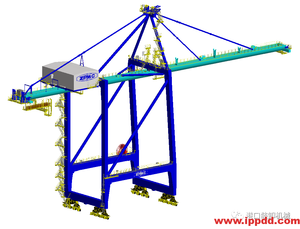
higher requirements in terms of civil engineering at terminals. Larger crane parameters need higher allowable wheel loads and stronger anchor devices. Particularly at exposed seaports, the influence of wind on equipment has always been a hot topic.
In the process of optimising the crane structure, ZPMC always considers the influence of wind as a key factor. Therefore, it has developed a new structural design concept called the ZMH semi-circular girder STS, named after the chief designer of this concept,Mr Zhang Ming Hai, who is also the chief designer at ZPMC.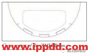
The new boom is constructed from a flat upper plate, the web of the rail support beam under the upper plate,and an arc-shaped plate butted with the web. The upper plate is a horizontal straight plate extending longitudinally.
The trolley rail support beams are located at both ends of the upper plate in the widthways direction, and the butt joint between the web of the rail support beam and the upper plate is located directly below the trolley rail.
The angle between web and upper plate is approximately 90 degrees. In this way, the stress can be effectively transferred, and it is convenient to butt with the arc-shaped plate.
The arc-shaped plate is spliced from flat plates, then bent into the required shape,and butt welded on the extension line of the web plate of the rail support beam.
The inside of the girder also includes longitudinal steel stiffeners and
U-shaped steels penetrating in a longitudinal direction, as well as diaphragms arranged at intervals longitudinally. This achieves a cross-section which is similar to a semi-circular shape (see diagram above).
With a semi-circular shape, the boom hinge can be placed under or above the upper surface of the girder in the form of a single hinge, which is simple, structurally compact and convenient for routine maintenance.
The trolley rail is installed on the upper surface of the girder, so as to ensurethe accuracy of manufacturing and installation, to avoid the need for later adjustment. Furthermore, the trolley rail can be welded on the rail support beam,which considerably reduces maintenance work required by eliminating rail clamps and rail pads.
monobox boom crane. Theoretically, the design could lower the total height of the crane slightly compared with a monobox design, as the bottom surface of the new boom is a curved shape, allowing more room on both sides to install a festoon or energy chain and floodlights.
The boom design can accommodate different trolley drive machinery and rope systems, including a full rope-towed trolley if requested by the customer.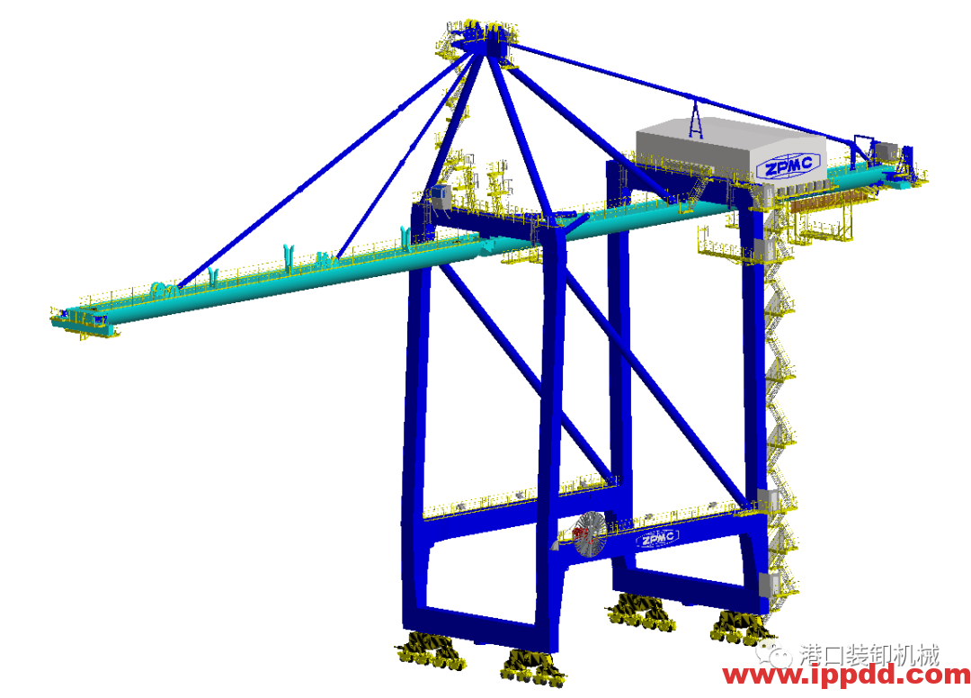 Weight/wind loads
In terms of its weight, the new girder is similar to existing monobox girder designs, which ports are familiar with, from an operational and management perspective. Compared with a double box girder boom, the weight can be reduced by 5%-10%.
Considering a double box girder boom with a 230t self-weight, the
weight reduction of the new boom will be around 17t. The new girder is available for different large capacity hoist systems, including dual hoist systems for tandem container handling.
With the decrease of the wind coefficient, the wind force acting
on the boom also decreases. This allows the boom to be constructed with thinner plate thickness than a conventional box girder boom, while still meeting the same storm conditions.
The reduction of the wind force coefficient has a greater effect on the crane under stowed conditions. With the development of our understanding of the effect of wind on structures, authoritative standards are using gradient wind to evaluate the safety of cranes.
greatly increased, and the higher the height, the greater the wind influence. It can be seen that reducing the wind load of the boom is of great significance to the whole crane.
● Crane 1 has an outreach of 65m, rail gauge of 30m, backreach of 20m, a lifting height above rail of 45m and a rated load of 65t.
● Crane 2 has an outreach of 50m, rail gauge of 30m, backreach of 16m, a lifting height above rail of 38m and rated load of 61t.
to analyse differences in wheel load data resulting from the application of the new girder. The results are shown in the accompanying tables.
conclusions: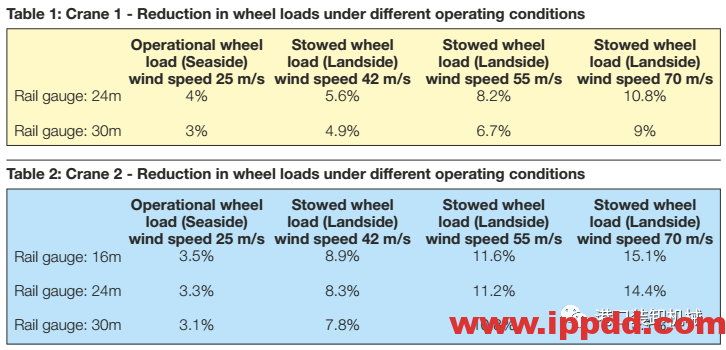
● The reduction in wheel loads is more obvious when the crane
is under stowed conditions. The higher the wind speed, the greater the reduction in wheel loads.
● For STS cranes with a narrow rail gauge, where the wind force has a greater impact on the wheel loads of the whole crane,the advantage of using this type of crane is more pronounced.
Generally speaking, STS cranes with this new structure can lower wheel loads by 5%-15% compared with the conventional double girder design.
ZPMC is the largest equipment manufacturer in the port machinery market, and its technical team is committed to providing customers with better products and value-added services through technical innovation.
The company has completed theoretical research of this new model and is steadily advancing demonstrations of all the details.We are looking forward to cooperating with interested customers.Next, we are planning to apply this model to RMGs and other types of yard handling equipment, so that this design concept can be even more widely used.
免责声明:本文来源于Worldcargonews,仅代表作者个人观点,与港口装卸机械公众号无关。其原创性以及文中陈述文字和内容未经本站证实,对本文以及其中全部或者部分内容、文字的真实性、完整性、及时性本站不作任何保证或承诺,请读者仅作参考,并请自行核实相关内容。如涉及作品版权问题,请与我们联系,我们将根据您提供的版权证明材料确认版权。
本篇文章来源于微信公众号:港口装卸机械公众号
